
ryan
Members
-
Benutzer seit
-
Letzter Besuch
Alle erstellten Inhalte von ryan
-
Hello! I am trying to generate a torque-current curve for the NEMA 17 stepper motor I have using the Voltage/Current Bricklet 2.0 and a Silent Stepper Bricklet 2.0. I have a lever arm attached to the stepper motor, which is powered with 24V. However, every time my motor is stalled (the arm hits a load cell), the motor jitters as if it is skipping steps (as expected). Is there a way to make my motor not jitter when it is stalled and just draw the appropriate amount of current? What setting should I look into changing? Or is this not possible? Ideally, I'd like it to act like a stalled brushed or brushless motor and draw its stall current without vibrating so much at stall. Thank you!
-
Thanks for the response, batti! I did a little more debugging today and it actually does look like I need a bypass capacitor for the receiver. It also seems that the less soldering I do, the better. For some reason, data doesn't travel well over soldered connections I made (probably because they were poorly soldered? Not sure). I wired the same circuit I had done on the perfboard onto a breadboard with jumper wires (plus the extra bypass capacitor), and it seems to be working fine now. Sorry for bothering everyone! Turned out to be a circuit issue rather than a Tinkerforge-specific issue.
-
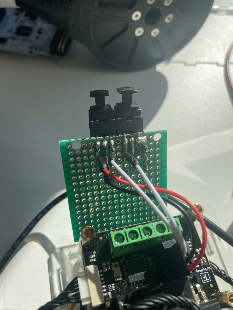
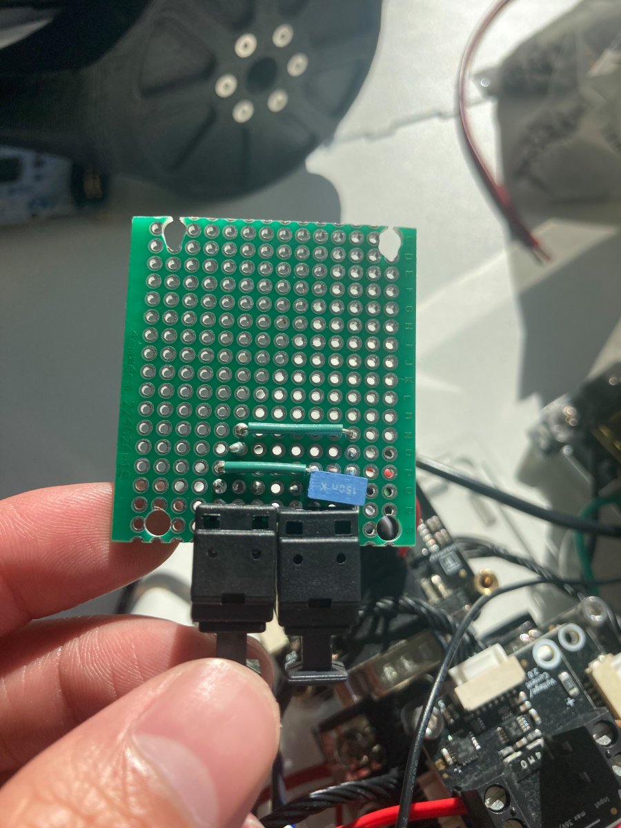
Hello all! I'm working on a project that requires data to be sent and received over optic fiber cables, specifically TOSLink cables. I have chosen the following transmitter and receiver from Sys-Concept: http://www.sys-concept.com/toslink_receiver_files/Toslink-TX-Data-16Mbps-Sys.Concept.pdf http://www.sys-concept.com/toslink_receiver_files/Toslink-RX-Data-16Mbps-Sys.Concept.pdf I have been able to connect two RS232 bricklets (V2) to a master brick, connect a receiver to the TTL interface on one RS232 bricklet and a transmitter (with a 150 nF bypass capacitor) to the other TTL interface, and send messages without a problem. Now, I am hoping to connect both a receiver and a transmitter to a single TTL interface on an RS232 bricklet. I connected a single transmitter to the other RS232 bricklet and sent a message to the receiver/transmitter combo just fine. However, when I connected a single receiver to the other RS232 bricklet and sent a message from the receiver/transmitter combo, the transmitter appears to just send a stream of never-ending gibberish over the TOSLink cable. In short, the circuit I have built involves connecting the 3.3V pin to both Vcc pins on the receiver and transmitter, the ground pin to both GND pins on the receiver and transmitter, and the RX1/TX pins to their respective Vin pins on the receiver/transmitter (see attached photos). I put a 150nF bypass capacitor between the Vcc and GND pins on the transmitter.This entire circuit is soldered on a perfboard. I was thinking I might need a bypass capacitor for the receiver, but the receiver didn't need one when a single receiver was attached to the TTL interface. Any suggestions, advice, or insight on what might be happening would be great! I pretty new to electronics like this, and I wasn't quite sure where I could get help because there isn't too much information online, so I thought I would try here. I am happy to provide any more information that is needed. Thank you! Sincerely, Ryan