blackfox
-
Gesamte Inhalte
20 -
Benutzer seit
-
Letzter Besuch
blackfox's Achievements
")
Newbie (1/14)
0
Reputation in der Community
-
Controll und überwachen Tinkerforge Bricks mit ScadaBR
ein Thema hat blackfox erstellt in: Projektvorstellungen und Projektideen
Ich habe mit ScadaBR seit etwa 3 Jahren gearbeitet und für den letzten 8 Monaten auch mit Tinkerforge http://sourceforge.net/projects/scadabr/. Ich installierte es auch auf einem Raspberry Pi und es funktionierte wie ein Charme. Es ist ein Open-Source Scada System http://de.wikipedia.org/wiki/Supervisory_Control_and_Data_Acquisition Ich übersetzte die Portugiesischen Handbuch in Englisch, aber die Grafiken werden noch vermisst (außerhalb meiner Kontrolle), aber Sie können sie in der Original Handbuch finden. http://sourceforge.net/p/scadabr/wiki/browse_pages/. Ich habe versucht Tinkerforge als Datenquelle zu bekommen aber ohne Erfolg. http://www.scadabr.com.br/?q=node/717 Ich fühle, dass ScadaBR ein Projekt ist das wirklich mehr Aufmerksamkeit verdient vor allem mit einer Community wie Tinkerforge, da sie sehr komplementär sind. Sie bitte über diesen Link antworten http://www.tinkerunity.org/forum/index.php/topic,2074.0.html -
Controll and monitor Tinkerforge Bricks with ScadaBR
ein Thema hat blackfox erstellt in: Project introductions and project ideas
I've been using ScadaBR for about 3 years now and for the past 8 months also with Tinkerforge http://sourceforge.net/projects/scadabr/. I installed it also on a Raspberry Pi and it worked like a charm. It's an Open Source Scada system http://en.wikipedia.org/wiki/SCADA. I translated the Portuguese Manual into English but the graphics are still missing (beyond my control) but you can find them in the original manual. http://sourceforge.net/p/scadabr/wiki/browse_pages/. I've tried to get Tinkerforge included as a data source but without success. http://www.scadabr.com.br/?q=node/717 I feel that ScadaBR is a project that really deserves more attention especially with a community like Tinkerforge since they are very complementary. -
Raspberry Pi - Step-Down Power Supply - USB Shield
Thema antwortete auf blackfoxs blackfox in: Project introductions and project ideas
Hi photron, Yes you're right about the USB part. The reason why I suggested it was to make the shield commercially more attractive by adding some features to it. Things that could be added to the shield are a Real Time Clock and a SD Card Reader/Writer. The reasoning behind the SD Card Reader/Writer is the following: On the RPi the operating system is the IPE – Industrial Perennial Environment a special blackout-proof flavor of Raspbian – a Debian-based Linux Distribution for the Raspberry PI. See http://nutcom.hu/?page_id=108 This solution keeps the SD card on the RPi intact for a very long time and the SD card on the shield is used for writing data. With these two features and Tinkerforge bricks, a simple standalone data logger can be created. But I guess that this could also be achieved with a Brick or Bricklet(s) that have an RTC and a SD Card Writer. This makes really sense when power consumption is a factor because the RPi's power consumption is fairly high compared to i.e. an Arduino. -
Raspberry Pi - Step-Down Power Supply - USB Shield
Thema antwortete auf blackfoxs blackfox in: Project introductions and project ideas
You are 100% correct and I use this setup as well, but it's a messy and far from compact solution. But besides those objections, the main advantage of using a step-down power supply is that you could use a 12V or 24V PS and with those PS's I can power devices that require those voltages and use Tinkerforge bricklets to read the values of the sensors of those devices and power the RPi, all in one compact setup. A powered USB setup works, but than I would need two PS's one of 5V and a bulky powered USB hub and another PS of let's say 12V or 24V to power my device. I proposed this because the RPi is a very popular board and I saw that a lot of people were using them with Tinkerforge, but in the mean time I stopped using them and I switched to the more powerful and versatile beaglebone black. -
Question about Analog In Bricklet Specs.
Thema antwortete auf blackfoxs blackfox in: General Discussion
Hello Photron, This is what I did in PHP <?php require_once('Tinkerforge/IPConnection.php'); require_once('Tinkerforge/BrickletAnalogIn.php'); use Tinkerforge\IPConnection; use Tinkerforge\BrickletAnalogIn; $host = 'localhost'; $port = 4223; $uid = 'di9'; // Change to your UID $ipcon = new IPConnection(); // Create IP connection $ai = new BrickletAnalogIn($uid, $ipcon); // Create device object $ipcon->connect($host, $port); // Connect to brickd // Don't use device before ipcon is connected // Sets the measurement range. Possible ranges: 0 to 5 $range = $ai->setRange(5); // 5: 0V - 3.3V, ~0.81mV // Get current voltage (unit is mV) $voltage = $ai->getVoltage() / 1000.0; echo "Voltage: $voltage V\n"; echo "Press key to exit\n"; fgetc(fopen('php://stdin', 'r')); $ipcon->disconnect(); ?> I added the following lines to the Simple Example in PHP // Sets the measurement range. Possible ranges: 0 to 5 $range = $ai->setRange(5); // 5: 0V - 3.3V, ~0.81mV This seems to work but since I'm not that experienced with programming there may be a better way to do this -
Question about Analog In Bricklet Specs.
Thema antwortete auf blackfoxs blackfox in: General Discussion
Hello Photron, I update to version 2.0.3 but I don't find a "new" range in the Brick Viewer. Does the Brick Viewer need to be updated as well in order to see that new range? -
Ambient Light Bricklet influences Analog In Brickelet
Thema antwortete auf blackfoxs blackfox in: General Discussion
Hello Photron, I'm using V2.0. I agreed with what he said, but it turned out not to be the problem. That's great, you found the problem and a good solution that works. Thanks for all your help. -
Ambient Light Bricklet influences Analog In Brickelet
Thema antwortete auf blackfoxs blackfox in: General Discussion
Hello Loetkoben, I noticed a problem with the Analog In Bricklet which seemed to react to changing light, since there is also a Ambient Light Bricklet on that Master Brick it seemed logic that there was a connection between the two. I also want to emphasis that the A.I. Bricklet reacted exactly the same way with a sensor connected or without a sensor (floating). I followed Photron's advice and swapped ports and this seemed to solve the problem. Following your message I decided to do a test with shielded cables and my original configuration. The result was almost exactly the same as with the standard cables (the effect of the Ambient Light Bricklet was still there). Than I tried the shielded cables and the new configuration (the one I used after Photron's advice) but the result was not the same as with the standard cables. (but the effect of the Ambient Light Bricklet was gone) I ended up by removing everything (cables as well) from the Master Brick except the A.I. Bricklet (with directly connected VIN and GND) and tested it with different standard and shielded cables and tried all the ports. The shielded cables gave a different result to the standard cables. With a shielded cable I only get a 0mV reading when the range is set at 0-10V, all other ranges gave me 3 to 5mV reading. With the standard cables I got a 0 to 1mV reading for the 0-6V and 0-10v ranges and the two other ranges give more eratic higher values. I could not find a difference between all the standard cables or all the shielded cables, and the different ports also gave no difference. Unfortunately I don't have multiple A.I. Bricklets nor Master Bricks to do more tests. -
Raspberry Pi - Step-Down Power Supply - USB Shield
ein Thema hat blackfox erstellt in: Project introductions and project ideas
A Raspberry Pi and a Master Brick is in many situations a very useful combination. But unfortunately there is a serious voltage drop of ±20% in the Raspberry USB. Adding a Step-Down Power Supply solves that problem but adds more cables. My idea was that a Step-Down Power Supply Shield for the Raspberry would make this much neater. And adding a USB port to that shield would give the options to have a properly powered Master Brick local on the shield or remote via USB to keep it compact, or a second Master Brick via USB. -
Ambient Light Bricklet influences Analog In Brickelet
Thema antwortete auf blackfoxs blackfox in: General Discussion
Hi Photron thanks for your help. Let me clarify this: This question is actually not relevant because it only happens with the bricklet in a conflicting port, so I shouldn't have asked it in the first place. I only let it float eventually to test the situation and to eliminate other causes for the problem. But I noticed the problem with a sensor connected in the first place. What's maybe more relevant is a sort of Rule of Thumb, by which conflicting Bricklets are correctly installed, and also which Bricklets are potentially conflicting. -
Ambient Light Bricklet influences Analog In Brickelet
Thema antwortete auf blackfoxs blackfox in: General Discussion
F.Y.I. My specific Bricklet port combination: the Ambient Light Bricklet at port C and the Analog In Bricklet on port D. But I also got a Humidity Bricklet at port A and a Barometer Bricklet at port B I swapped the Analog In Bricklet to port A and the Humidity Bricklet to port D and the problem is fixed, at least for the Analog In Bricklet. The Value at the A.I. bricklet is now ± 8mV. But why was the value of the A.I. bricklet constant at ± 20mV by disconnecting the Ambient Light Bricklet in the original situation. -
Ambient Light Bricklet influences Analog In Brickelet
ein Thema hat blackfox erstellt in: General Discussion
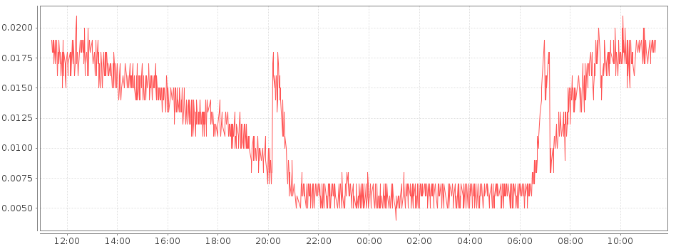
I found the behavior of the Analog In Bricklet strange: With no sensor connected to the A.I. Bricklet and Bricklet at 0-6V: When it's dark at night the A.I. Bricklet stays at ± 8mV. During the day with increasing light the value goes up, rises by ± 12mV to ± 20mV and drops again by night. During dawn and dusk there is a spike of ± 12mV. I found this to be the cause: Obscuring the Ambient Light Bricklet on the same Master Brick kept the value of the A.I. bricklet constant at ± 8mV. Disconnecting the Ambient Light Bricklet kept the value of the A.I. bricklet constant at ± 20mV. Is it normal that the output of the Ambient Light Bricklet influences the output of the Analog In Bricklet?
-
Question about Analog In Bricklet Specs.
Thema antwortete auf blackfoxs blackfox in: General Discussion
That's great at least there is a possible solution. Let me explain the motivation behind my original question. A lot of sensors produce an extremely low Vmax but at the same time amplification of the signal is not desired because this would adversely affect the measurement. The sensor in this case produces a Vmax of about 250mV and measurement needs to have a reasonable resolution of anything less than 0.80mV. The project I'm talking about http://www.instesre.org/construction/pyranometer/pyranometer.htm measures solar isolation and the effects aerosols have on it's intensity. Since that value is constantly changing, it would be great to know the actual conditions at any given time and place. I don't need to emphasis the importance of this in a today's world with it's need for natural and renewable energy sources. This could even be a Kit project from Tinkerforge as other values like temperature, pressure and RH also play a role in the whole process. -
Question about Analog In Bricklet Specs.
Thema antwortete auf blackfoxs blackfox in: General Discussion
We disabled the smallest range since there were problems with jumps in the measurements when a voltage of about ~3.3V (which is a common voltage) was measured. So if I understand this correctly it's been disabled because 3.3V is a value at which a lot of sensors happen to linger? Could a solution than be that the maximum value for the MAX_VOLTAGE_0 is set at lets say 2.5V or even lower, or does that require a hardware change as well? -
When I look at the spec-sheet for the analog in bricklet I find the following values: Voltage 0V - 45V in 1mV steps, 12bit resolution Measurement Range Automatically switched 0V - 6.05V, ~1.48mV resolution 0V - 10.32V, ~2.52mV resolution 0V - 36.30V, ~8.86mV resolution 0V - 45.00V, ~11.25mV resolution However when I look at config.h and the schematic of the bricklet I find this: #define VALUE_RESISTOR_0 0 // in in in #define VALUE_RESISTOR_1 12000 // gnd in in #define VALUE_RESISTOR_2 4700 // in gnd in #define VALUE_RESISTOR_3 1000 // in in gnd #define VALUE_RESISTOR_4 772 // gnd gnd gnd #define MAX_VOLTAGE_0 3300 #define MAX_VOLTAGE_1 6050 #define MAX_VOLTAGE_2 10320 #define MAX_VOLTAGE_3 36300 #define MAX_VOLTAGE_4 46071 Does this mean that this Bricklet has one more Measurement Range than published on the website namely: 0V - 3.30V, ~0.81mV resolution from: #define VALUE_RESISTOR_0 0 // in in in and #define MAX_VOLTAGE_0 3300 Please confirm this, it would be great if this is the case.