
borg
-
Gesamte Inhalte
3.628 -
Benutzer seit
-
Letzter Besuch
-
Tagessiege
63
Posts erstellt von borg
-
-
A Brick with more than 4 Bricklet connectors is quite hard. Bricks are defined to have a size of 4x4cm, 2 board-to-board connectors at the sides and one usb connector and 2 buttons at the front. 4 Bricklet connectors are unfortunately the maximum that can be mounted on the back side.
A larger board without stack capability with just a USB connector and lots of Bricklet connectors would be possible.
A Multi Analog IN Bricklet would also be possible.
I doubt that we will make any of the two in the next months however. There is so much more stuff we want to release, we have to prioritize.
Regarding the mounting kits: Mhh, i suppose the idea is that you get everything you need to be able to place a Brick/Bricklet on a table without the board touching it. It is hard to provide anything that might be needed to mount our stuff in any possible casing or similar.
That said, you can probably buy 3mm screws for something like 1 cent/piece at your local hardware store. Also we intend to offer casings for all of our Bricks/Bricklets in the future, there you will of course get anything needed.
-
Bei mir funktioniert der Source Code hier: https://pastee.org/gtnxq sowohl unter Linux (Ubuntu 11.10) als auch unter Windows 7 ohne Probleme.
Hast du die IO16 schon auf die neueste Firmware geupdatet? Hab da vor kurzem eine Kleinigkeit hinzugefügt, siehe hier: http://www.tinkerunity.org/forum/index.php/topic,188.0.html
(das kann aber eigentlich nichts mit deinen Problemen zu tun haben)
Funktioniert das denn im Brick Viewer? Einfach starten und auf die Knöpfe drücken, der konfiguriert dafür standardmäßig genau richtig.
Welche Version haben deine Python Bindings?
-
Oh, es leuchtet keine LED wenn du es per USB anschließt? Aber es taucht ein neues Gerät unter Windows auf? Klingt als wäre dein Servo Brick im Bootloader!
Dann musst du eine neue Firmware draufflashen, wie das geht ist hier beschrieben: http://www.tinkerforge.com/doc/Software/Firmwares_And_Plugins.html#flash-firmware-on-a-brick
Firmware fürs Servo Brick gibts hier: http://download.tinkerforge.com/firmwares/bricks/servo/
-
OK, nochmal zum Thema Kalibrieren (das Kalibrieren unter "advanced functions").
Wenn man dort auf "calibrate" klickt, werden die Extremwerte des Analog zu Digital Wandlers vom Brick kalibriert. Das hat an der Stelle erstmal überhaupt nichts mit den Bricklets zu tun!
Nun, um die Extremwerte (d.h. 0V und 3.3V in unserem Fall) zu kalibrieren, benötigen wir aber extern etwas, das diese Werte erzeugt. Da kommen die analogen Bricklets ins Spiel. Um den Analog zu Digital Wandler korrekt zu kalibrieren müssen wir also ein Bricklet anschließen mit dem wir auf dem analogen Pin 0V und 3.3V erzeugen können, dies geht z.B. gut mit den Potis. Dazu kann man ein Poti anschließen, auf einen Extremwert drehen, "calibrate" klicken, auf den anderen Extremwert drehen, "calibrate" klicken und fertig. Nun sind 0V und 3.3V kalibriert.
Diese Möglickkeit haben wir eingebaut da der Analog zu Digital Wandler auf dem Microcontroller nicht immer die vollen Werte erreicht. Da er eine 12 Bit Auflösung hat sollte er bei 0V 0 ausgeben und bei 12V 4095. Allerdings kann es sein das er sowas wie 2 und 4092 o.ä. ausgibt, dieser Fehler wird Kalibriert.
Wenn du den Analog zu Digital Wandler nun verkalibrierst (d.h. du drückst z.B. "calibrate" wenn das Poti nicht nach ganz links oder ganz rechts gedreht ist), gibt alles falsche Werte zurück was den Analog zu Digital Wandler benutzt. Unter anderem alle Analog Bricklets und die Spannungs- und Strommessung im Stack!
Um das nochmal ganz klar zu machen: Diese Kalibrierung wird auf dem Brick gespeichert und betrifft das Brick, das Bricklet mit dem kalibriert wird ist nur Hilfsmittel.
Wenn du aus welchen Gründen auch immer Probleme mit der Kalibrierung hast, würde ich sehr stark empfehlen das Brick neu zu flashen und einfach den "calibrate" Knopf unter "advanced functions" nicht zu drücken
 .
.Zum Thema Lux: Tageslicht hat 10000 Lux, dein Handy kann vermutlich 900 Lux erzeugen wenn du es genau drauflegst.
Zum Thema Ambient Light Kalibrieren: Das muss nicht kalibriert werden, wenn du etwas mehr über die genauen Eigenschaften des Sensors erfahren willst kann ich dir die Graphen im Datenblatt empfehlen: https://github.com/Tinkerforge/ambient-light-bricklet/raw/master/datasheets/TEMT6000.pdf
Edit: Die Bricklets die eine Kalibrierung benötigen (z.B. Current oder Distance IR) haben Kalibrierungsfunktionen dafür im jeweiligen Bricklet Fenster im Brick Viewer. Diese Kalibrierungen werden dann natürlich auch auf den Bricklets gespeichert.
-
Überprüfen welchen Interrupt du bekommen hast kannst du mit dem binären &, z.B.:
if value & (1 << 5):
    # hier code für pin 5 = high
if value & (1 << 0):
    # hier code für pin 0 = high
# ...
Ansonsten, ist mir noch nicht klar was du machen möchtest. Soll der Motor so lange fahren wie du den Knopf drückst?
Dann würde ich machen
# Schalter an Pin 5
if value & (1 << 5):
    stepper.drive_forward()
else:
    stepper.stop()
Wenn du pro Knopf drücken x Schritte fahren willst:
# Schalter an Pin 5
if value & (1 << 5):
    stepper.set_steps(x)
-
Naja, dafür musst du die Schrittanzahl die beim Poti eingestellt wird zwischenspeichern und sobald du den Callback bekommst den Wert mit set_steps setzen.
-
Puh, schwer zu sagen. Der Brick Viewer ist ja in reinem Python geschrieben, da sollte man so einfach eigentlich gar keinen Speicherzugriffsfehler erzeugen können.
Vielleicht ein Bug in der Qt oder PyQt Version von Ubuntu 12.04? Der strace ist leider nicht besonders hilfreich.
Wenn du lust hast kannst du mal in der mainwindow.py in MainWindow.__init__ (ab Zeile 67ff) Stück für Stück ein "return" einbauen und gucken ab welcher Zeile der segfault kommt.
So wie der strace aussieht passiert das vermutlich entweder schon beim setupUi oder sogar direkt beim import oben. Ob die imports gehen kannst du testen in dem du einfach python in der Console startest und die import zeilen dort ausführst:
from PyQt4.QtCore import pyqtSignal, QAbstractTableModel, QVariant, Qt
from PyQt4.QtGui import QMainWindow, QMessageBox, QIcon
-
Du meinst 1.0.6 oder? 1.0.7 gibts nicht
.Unter 11.10 hab ich das .deb gerade nochmal getestet, läuft.
Um den Brick Viewer aus den Sourcen zu starten musst du einmal build_all_ui.py (im src/brickv/ Verzeichnis) ausführen und vorher pyqt4-dev-tools installieren. Das baut die GUI aus den .ui Dateien.
Und dann wenns geht einmal in der config.py auf logging.DEBUG stellen und nochmal main.py ausführen. Dann bitte die Ausgabe hier nochmal posten, bin gespannt was der Fehler ist.
-
Hab mir mal gerade den IO16 Code kurz angeguckt. Das kann Zustande kommen wenn uns der IO Expander ein Interrupt erzeugt während wir in der debounce Phase sind (low -> high), dann das Interrupt wieder wegnimmt (high -> low) und dann ein neues Interrupt kommt (low -> high) bevor die debounce Phase zuende ist.
Ich hab mal eingebaut das der letzte Interrupt gespeichert wird um zu gucken das wir den gleichen nicht nochmal verarbeiten: https://github.com/Tinkerforge/io16-bricklet/commit/147ad1f617c766313edaf5461f9eee5efe498b25
Ob das dein Problem zu 100% löst kann ich nicht sagen, schaden tut es aber nicht.
Hier gibts die neue Version: http://download.tinkerforge.com/firmwares/bricklets/io16/bricklet_io16_firmware_1_1_1.bin
-
@nikwest
Habe gerade eine neue Master Brick Version (1.1.4) und eine neue Brick Viewer Version (1.0.6) hochgeladen, diese implementieren es jetzt so wie du es vorgeschlagen hast. So wie es vorher war, war es einfach nicht verständlich genug.
Hier ist die neue Dokumentation dazu: http://www.tinkerforge.com/doc/Hardware/Master_Extensions/Chibi_Extension.html#chibi-configuration
Da gibt es jetzt denke ich nichts mehr misszuverstehen!
-
No idea what is going on there. There is no way to install python 2.4 on any of the systems i have here (other then compiling it from source), but there is nothing that could be considered a syntax error in any python version at that location.
-
In general i agree. But one of the groups our hardware is very appealing to are pupils that want to learn a programming language. With some Bricks and Bricklets thrown in, learning a programming language can be a lot more fun.
This group especially may not be comfortable in english and needs native language support.
Currently we are mostly selling to Germany (~80%). That is probably the case because of the bigger media respose we had in Germany. I expect that the numbers will shift in the future and then there will automatically be going on more in the english language forum.
-
python-gudev is needed for USB hotplug, you can use brickd without it (you have to plug in the Bricks before starting brickd in that case).
Regarding your traceback: Is that the complete traceback? It isn't saying anything.
Can you change the logging level to logging.DEBUG in config.py and then run brickd with ./brickd_linux nodaemon and post the outcome?
edit: I just did a quick search, it seems libusb1 and python-gudev is readily available as rpm:
http://rpm.pbone.net/index.php3/stat/3/srodzaj/1/search/libusb1
http://rpm.pbone.net/index.php3/stat/3/srodzaj/1/search/python-gudev
there are also rpm's for CentOS 6 in the list (i can't see any for 5.8 unfortunately).
-
Oh! D.h. da muss etwas eingestellt gewesen sein was nicht erlaubt ist, die frage ist natürlich wie das passiert ist.
Entweder das EEPROM hatte im Auslieferungszustand nicht überall 0xFF stehen (was es eigentlich haben sollte) oder es ist irgendwo ein Bug den du getriggert hast der dafür gesorgt hat.
Wenn das gleiche Problem nochmal auftritt bitte Bescheid sagen und posten was du gemacht hast bevor es aufgetreten ist
. -
Klingt so als seien auf den Bricklets die Plugins nicht OK. Der Brick läd die Plugins, führt sie aus und stürzt ab. Deswegen blinken dann die LEDs auch nicht.
Kannst du mal versuchen die neu zu flashen?
Dazu das Brick per USB anschließen, dann das Bricklet anschließen (in der Reihenfolge bitte nur machen um neu zu flashen), dann auf "Advanced Functions" und das entsprechende Plugin und den passenden Port auswählen und auf Save klicken.
Davor bitte die neueste Brick Viewer Version installieren, unter Windows gab es vor Version 1.0.3 Probleme beim Plugin flashen:
http://download.tinkerforge.com/tools/brickv/windows/
-
How many 240V devices do you have attached to the Dual Relay Bricklets? Does this happen with one already?
And what do you use to power the Master Brick? I expect that the Master Brick does not get enough power through the USB port in your case. There is a thread in the German forum with a similar problem, he could get it working with a Step-Down Powersupply.
-
Wir haben im Moment das Problem, dass der Brick Viewer beim drücken von bestimmten Buttons (die eigentlich gar nichts böses tun) abstürzt. Aber nur wenn wir eine .app draus gemacht haben, wenn wir aus dem Source starte gibt es keine Probleme.
Das bereitet uns ein wenig Kopfzerbrechen, da haben wir noch keinen Ansatzpunkt gefunden das zu fixen.
Bastian ist gerade nicht mehr hier, der kümmert sich um die Mac OS X Version. Vielleicht kann er aber heute Abend irgendwann eine kurze Anleitung schreiben wie man Den Brick Daemon/Viewer aus den Sourcen unter Mac OS X starten kann.
-
Mh, das klingt alles richtig. Kannst du mal ganz kurz die Frequenz auf etwas anderes umstellen zum testen? Wir kennen von einem Fall wo ein Funkthermostat auf der 868Mhz Frequenz so viele Daten sendet das bei Chibi zwischendurch Daten verloren gehen (allerdings funktioniert es dort prinzipiell erstmal).
Du hast jetzt zwei neue Master Bricks, oder? Da würde ich die Wahrscheinlichkeit als sehr gering einschätzen das es an denen liegt.
-
We added support for that in the Master Brick firmware version 1.1.3:
-
1. You support quite a few languages, but unfortunately my favorites aren't there. Are you planning any support for Perl and PHP? Especially on the Linux platform there are lots of programmers using these two. PHP would be great for web integration.
Currently we are working on OS X support and the RS485 Extension, after that we will probably make the firmware for the Encoder Bricklets (they make the driver Bricks a lot more usefull) and then i intend to add more languages.
2. I understand that the API's talk TCP to a brickd daemon. It's easy to do TCP connections in (almost?) any language, so if the brickd TCP protocol is documented we could use that instead of the API. (or write our own API)
Yes, it is probably a good idea to document the protocol we are speaking. It is certainly possible to speak the protocol in every language, there is no magic involved.
3. There are standards for talking to hardware via the filesystem in Linux (/sys/class or /proc). Have you considered using these?
That way controlling bricks and bricklets could be as easy as:
echo 1 > /sys/class/bricklets/dualrelay1
echo "Hello world" > /sys/class/bricklets/lcd1/line1
Or reading as easy as:
cat /sys/class/bricklets/analog1
It's not so easy to do events this way, but for simple polling or controlling this would do very nicely. You would immediately have added support to every language available on the Linux platform.
One of our very first ideas was that a Brick could anounce itself as a mass storage device to the PC with a filesystem as described by you. But, as you said the events are problamatic and the events are very very important if you want any kind of performance over USB. For example if you have a few sensors in a stack over USB and you want to control a motor at the same time, you will be amazed how little bandwith there is left for the motor controlling if you are polling the sensors with a high frequency. Where as events with e.g a period of 10ms per sensor wouldn't be any problem.
However, it would be possible to write another daemon that sits behind the Brick Daemon and generates a /sys like filesystem that can be used from everywhere. It probably would have a lot in common with the generators we use to generate the language bindings. So if there is someone that would be interested in writing something like this, i would certainly help if there are questions or problems.
-
die neue die [...] hat neben dem 6-27V Eingang auch noch einen 5V Ausgang (exakt für Sachen wie das Beagle Board oder das Raspberry Pi).
Macht es dabei eigentlich Probleme, dass die Bricks und der PC gleichzeitig Strom bekommen. Ich nehme mal an, dass die Bricks deutlich schneller hochgefahren als der PC, und somit nicht wissen ob sie an einem PC hängen oder nicht?
Gute Frage, da hab ich noch nicht drüber nachgedacht. Man kann natürlich wenn das Linux Board hochgefahren ist beim Master einmal auf Reset drücken, dann läufts.
Rein softwaretechnisch ist es aber denke ich auch möglich den Bricks USB-Hotplug beizubringen (d.h. ein Brick wechselt vom Slave in den Master Modus wenn es an ist und man USB dransteckt). Das wirft dann natürlich Fragen auf: Was ist mit einem Brick das im Slave Modus in einem Stack ist der über USB angeschlossen ist? Wenn ich da USB dran anschließe, was soll dann passieren?
-
@gunter das Encoder Bricklet steht in der TODO Liste nach OS X Support und RS485 Extension
@redieck: Wir verkaufen im Moment noch alte Step-Down Powersupplies aber die neue die gerade in Produktion ist hat neben dem 6-27V Eingang auch noch einen 5V Ausgang (exakt für Sachen wie das Beagle Board oder das Raspberry Pi).
-
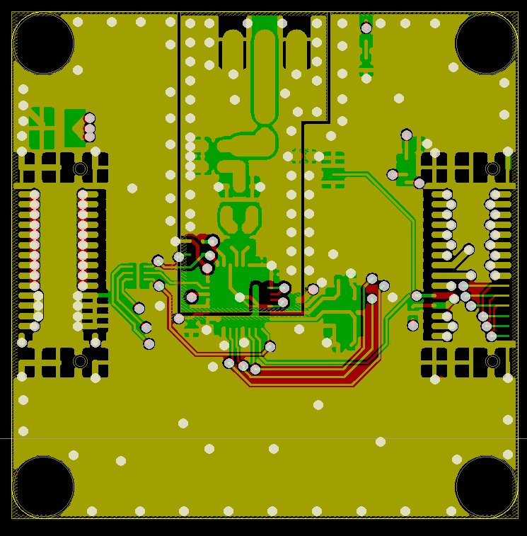
Du kannst den Master Stack nach neuen Chibi Teilnehmern suchen lassen indem du auf den Reset Knopf drückst.
Bzgl des Platzes am unteren Rand der Chibi Extension: Sieht für mich so aus als würde da keine Leiterbahn durchgehen, hab mal das Layout mit allen relevanten Lagen angehängt.
-
Hehe, innerhalb deutschlands kann ich mir gut vorstellen auf dauer auch einen Paketdienstleister zu benutzen. Bisher hatten wir einfach nicht die Zeit da mit einem zu verhandeln. Ich könnte mir aber gut vorstellen das wir uns da drum kümmern wenn jetzt die ganzen Vorbestellungen raus sind.
Ins Ausland sind die Einschreiben für uns allerdings wirklich super. Wir haben den Vorteil das unsere Produkte klein und leicht sind, d.h. wir können sie als Maxibrief (unter 500g) ins Ausland schicken für schlappe 3,45€ (7€ für 500-1000g) dazu kommen dann jeweils noch 2,05€ für das Einschreiben. Dafür wird aber z.B. eine Sendung nach Australien in unter 5 Tagen verschickt!
Zum vergleich: Ein DHL Paket nach Australien kostet 42€ und dauert 11 Tage!
Was ein Express DHL Paket nach Australien kostet will ich hier gar nicht sagen, das würde mir eh keiner glauben: http://bit.ly/wHvVco
.Edit: Ganz Allgemein verschicken wir natürlich als Einschreiben damit wir einen Nachweis darüber haben das wir es abgegeben haben und auch einen Nachweis bekommen wenn es angenommen wurde. Versichert sind Einschreiben auch bis zu einem bestimmten Betrag.
 .
. .
.
Too many bricks & bricklets, not enough screws
in General Discussion
Geschrieben
They would fit there, but the connectors of the Bricklet cables would collide with the USB connector on a USB cable (about 1mm with the cables we are currently selling).